Remote control for NooElec Ham It Up HF upconverter using Raspberry Pi
In this post I will be building a simple, relay-based controller for NooElec Ham It Up upconverter to allow enabling and disabling the HF upconverter with software by using Raspberry Pi to control the relay.
My SDR setup
I have been using a simple software-defined radio (SDR) setup for a couple of months, mainly for listening to amateur radio (HAM) bands and decoding weather satellite images so far. The setup includes an RTL-SDR-based NooElec NESDR SMArt USB-dongle, a NooElec Ham It Up v1.3 upconverter (and its case) and a Raspberry Pi 3. The upconverter is required in order to access HF bands, since the RTL-SDR dongle tuners only support frequencies down to ~25 MHz.
Ham It Up upconverter modification
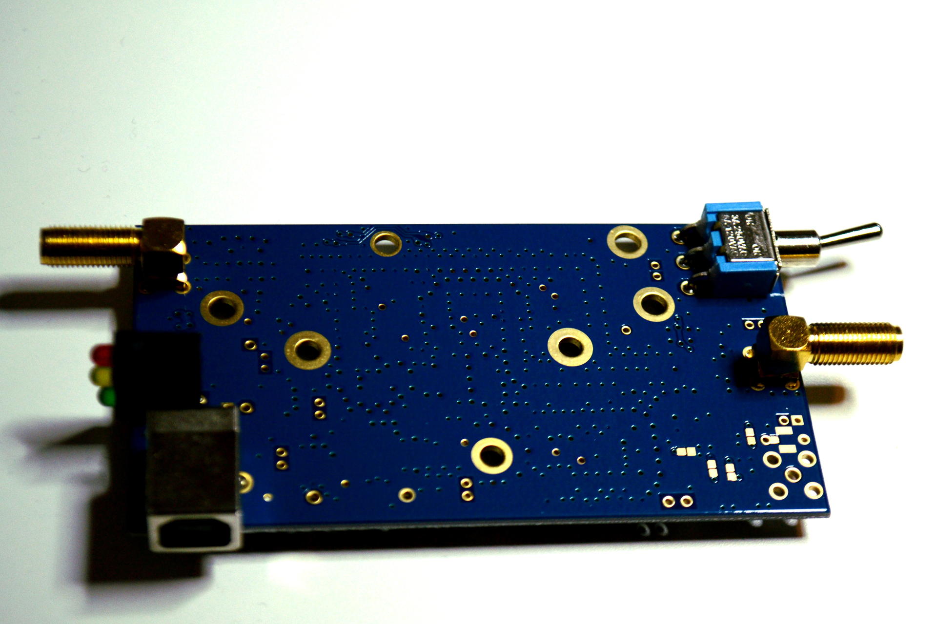
NooElec Ham It Up v1.3 upconverter board
The Ham It Up v1.3 upconverter converts frequencies from range 0.5-50 MHz to 125.5-175 MHz (see the technical documentation) to allow reception of lower frequencies with limited SDR tuner hardware, like with RTL-SDR-based receivers. The upconverter has a physical switch to enable and disable the upconverter, so there is no need to disconnect it when turning off conversion (into pass-through mode), but it is not possible to control it remotely.
The solution for remote control of the upconverter is simple: connect a low-voltage relay to the upconverter switch and use a single-board computer, such as Raspberry Pi, to provide the control signals to the relay. This modification to the upconverter does not require changing or removing existing components on the upconverter board and is reversible!
Components
Basic components:
-
1x Raspberry Pi B+/2/3
-
1x Raspberry Pi enclosure with extra space: ModMyPi Modular RPi 2/3 Case
-
Add 2 spacer plates to provide for extra room for the HAT and wiring
-
Components necessary for relay control:
-
1x 5V (TTL-level) relay module: HL-52 2-relay module
-
1x 5V I²C output port expander: ModMyPi MCP23017 32 Channel I/O Expansion HAT
-
3-4x 0.1" female-female jumper wires
-
2x 20-40 cm ~0,22 mm² wire to be soldered to the upconverter switch
Relay module
I found a cheap 2-relay module called HL-52 for this application, but any relay that works with 5V signals (TTL-level logic) should be suitable for this purpose. The only limitation here is that the relay should optimally support inverted wiring that shorts the relay terminals by default (when relay is "off"), and disconnects them when it relay is "on". This is because of the way the upconverter switch is wired: in order to control the switch mode with an external relay, while still having the switch connected to the upconverter board, the upconverter must be left turned on. By shorting two of the three pins of the switch the upconverter can be put into pass-through mode, turning it off.
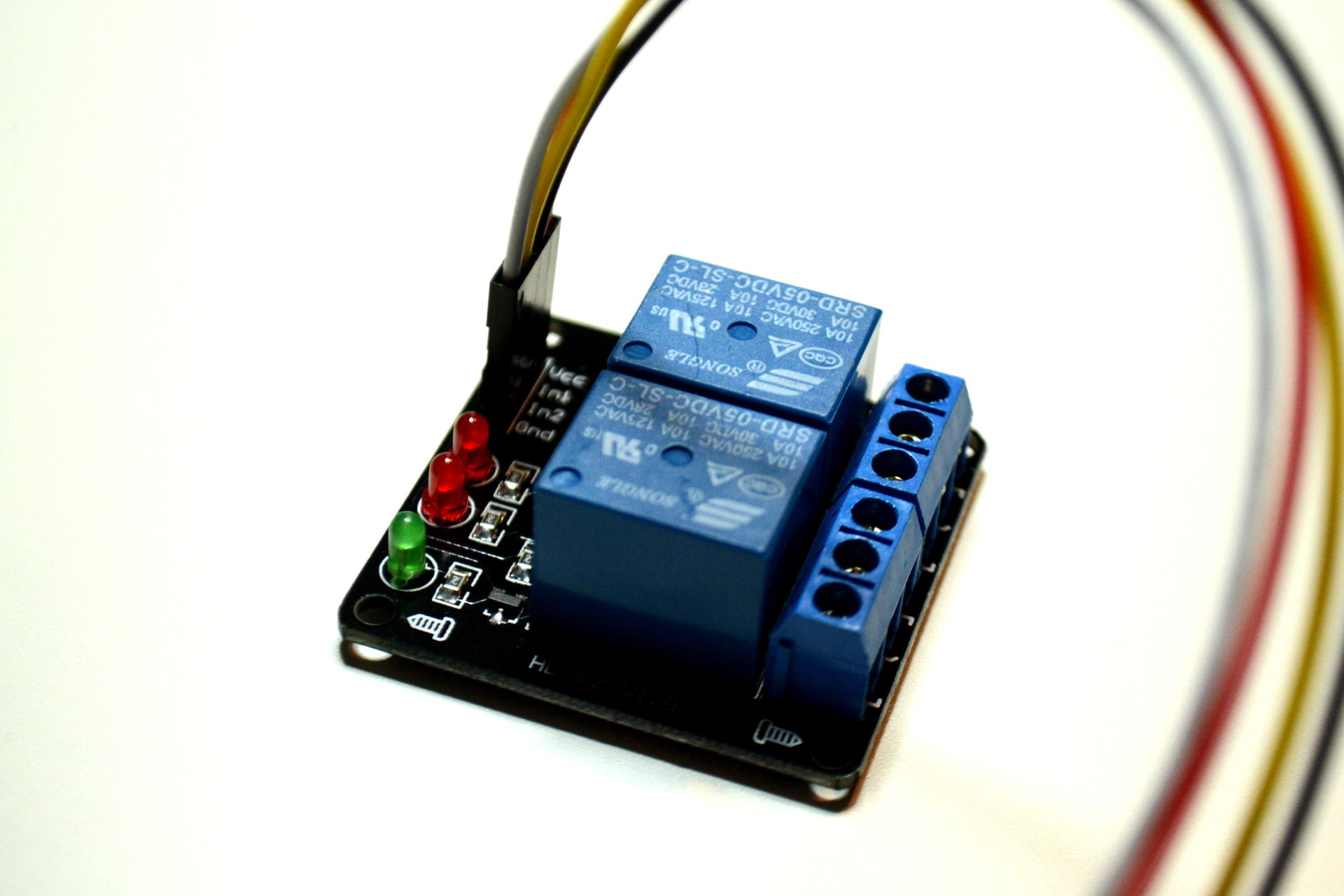
HL-52 1.0 2-relay module
I/O expansion HAT
While the relay could be connected directly to Raspberry Pi GPIO pins, I chose to use an additional I/O expansion HAT for Raspberry Pi to protect the core RPi chip and to have additional pins available for future projects. Again, the I/O expansion module could be any buffer or I²C/SPI module driving pins at 5V TTL-level voltages. The WiringPi library provides driver code for the MCP23017 module available, for example, in the ModMyPi MCP23017 32 Channel I/O Expansion HAT.
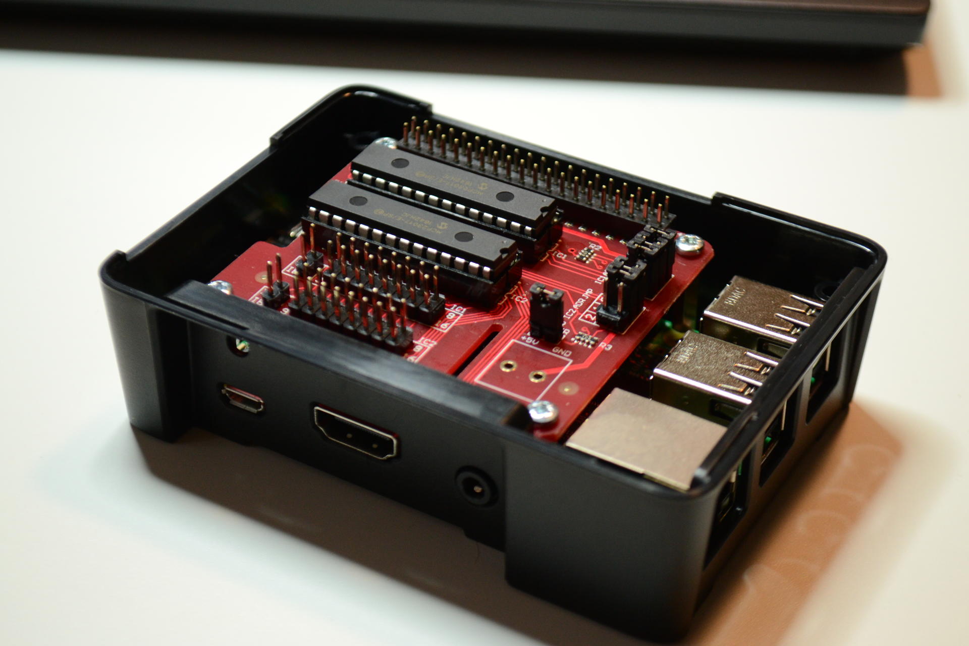
ModMyPi MCP23017 32 Channel I/O Expansion HAT mounted on Raspberry Pi 3
The Raspberry Pi case in the picture is a ModMyPi Modular RPi 2/3 Case with 2 spacer plates to provide for extra room for the HAT and wiring.
Assembling the components
There should be no need for an optical isolator, because the voltage level is roughly the same on the upconverter and Raspberry Pi. Dangerous mains-level voltages are not used here. :)
1. Connect relay to Raspberry Pi

MCP23017 HAT pins 1-2 and 5V power from Raspberry pi connected to HL-52 relay board
Connect the the relay to Raspberry Pi pins using female-female jumper wires:
-
Raspberry Pi pin 2 (
5V) → relay pinVCC -
Raspberry Pi pin 6 (
GND) → relay pinGND -
MCP23017 I/O pin 1 → relay pin
In1 -
MCP23017 I/O pin 2 → relay pin
In2
The second relay is left unused in this case. I was planning to use it to control power to the upconverter, but it turned out to be quite difficult to get access to the USB power without modifying the PCB. Another choice could be to use a modified USB cable or connector that would allow switching off USB power.
2. Solder wires to upconverter switch
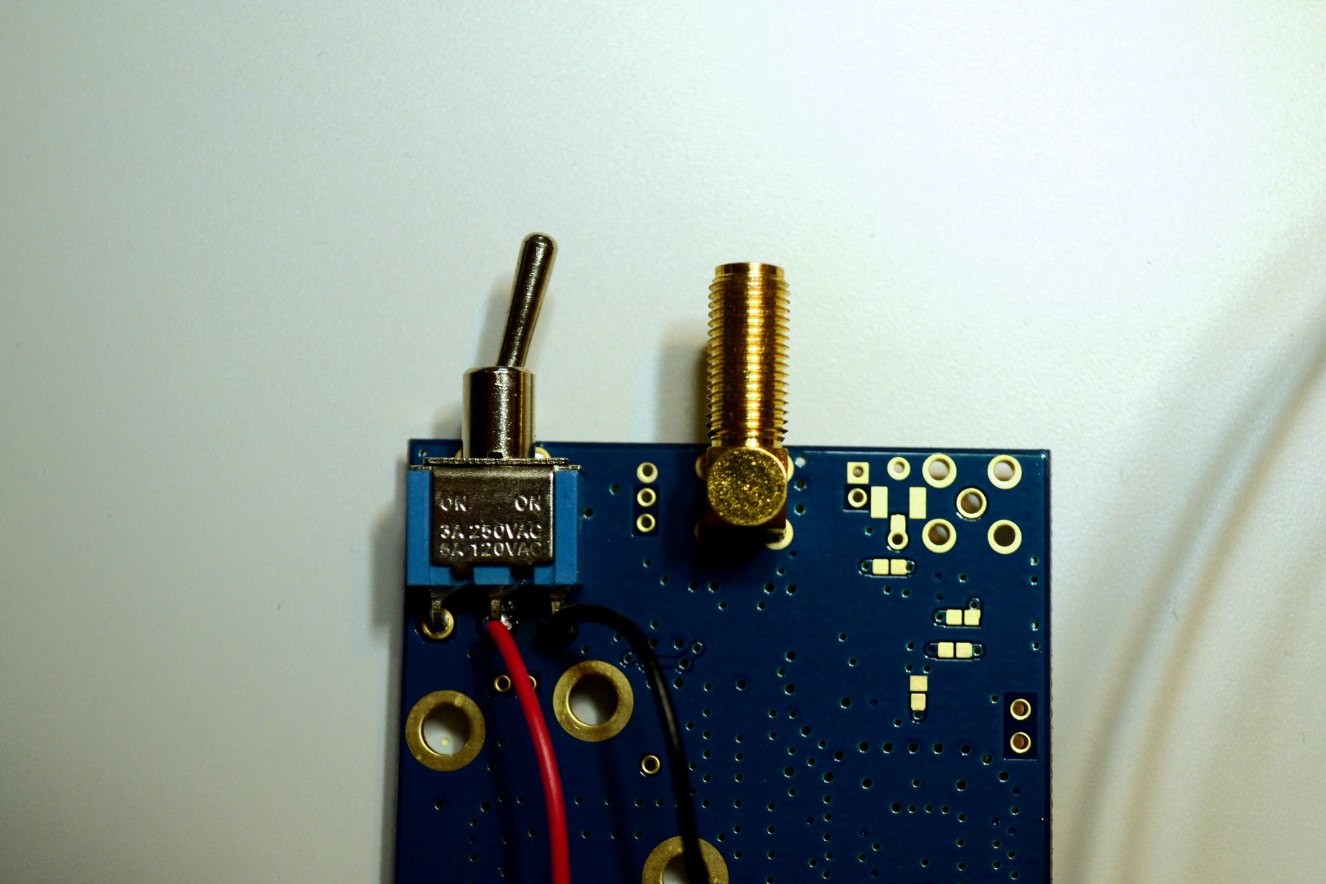
Wires soldered to the upconverter switch (closeup)
Solder wires to pins 2 and 3 of the switch (counting from left when the switch is facing up).
The switch is a regular ON-ON switch, where pins 2 and 3 have to be shorted to turn the converter off. In order to make the modification work with the switch, the switch has to be turned to position where the upconverter is active, shorting pins 1 and 2. This allows the signal level entering the switch circuitry to be set to low (GND), because the third pin is connected to ground. The v1.3 board schematic confirms this. Shorting all of the three pins of the switch may not be an ideal solution, but it seems to work :)
3. Assemble Ham It Up enclosure
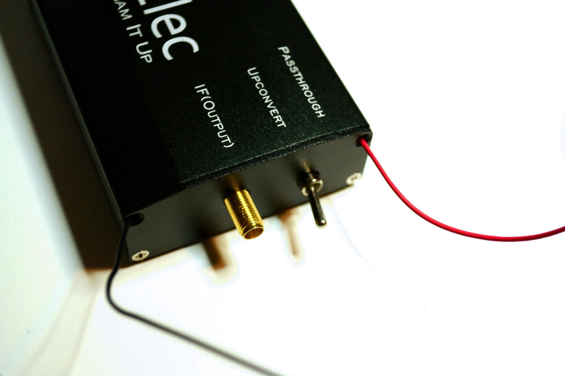
The wires can go through screw holes of the upconverter enclosure
To avoid drilling additional holes to the enclosure, I used two of the holes for screws on one side of the enclosure to bring out the wires.
4. Connect upconverter switch wires to relay
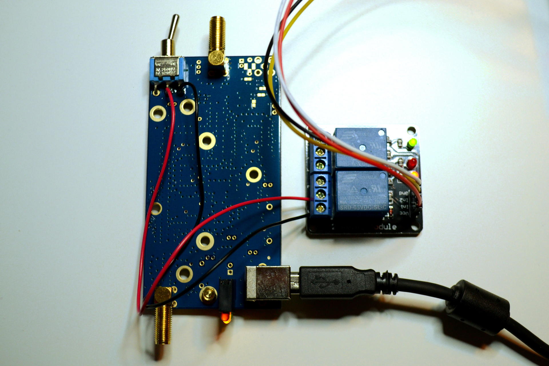
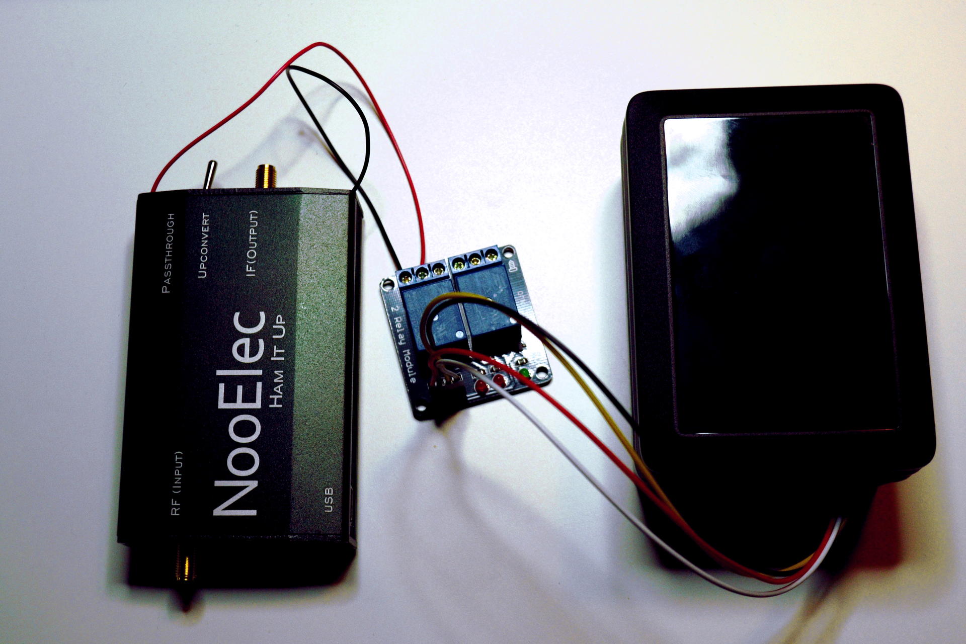
Wires from to the upconverter switch connected to relay
Simply connect the wires from the upconverter switch to the relay (the photo was taken before I installed the enclosure). Pay attention that the wires have to be shorted by the relay by default if you wish to have the upconverter to be off and inactive when powering up the relay.
5. Assemble Raspberry Pi enclosure
Final result with enclosures for the upconverter and Raspberry Pi
I did not plan to have any additional protection or an enclosure for the relay yet, as all of the hardware here will be placed in a wooden cabinet and there is no need to move it around.
Controlling the relay
The WiringPi library that is commonly used to control Raspberry Pi GPIO pins also provides a driver for the I²C-bus-based MCP23017 I/O expansion chip. Since we only need to control the state of a single pin, it is convenient to use a short Python script to perform the action, as Python has bindings to the WiringPi library.
First, as per the official instructions, install Python development tools and WiringPi bindings:
sudo apt-get install python-dev python-pip
sudo pip install wiringpi
Next, copy the following script to a file called switch-upconverter.py:
#!/usr/bin/python

import sys
import wiringpi as wiringpi

# set the base number of ic1, this can be any number above (not including) 64
ic1_pin_base = 65
# pin number to code number:
# 1 = 65, 2 = 66, 3 = 67, 4 = 68, 5 = 69, 6 = 70, 7 = 71, 8 = 72, 9 = 73, 10 = 74, 11 = 75, 12 = 76, 13 = 77, 14 = 78, 15 = 79, 16 = 80
# define the i2c address of ic1, this is set by the jumpers on the HAT
ic1_i2c_addr = 0x20

# initiate the wiringpi library
wiringpi.wiringPiSetup()
# enable ic1 on the mcp23017 hat
wiringpi.mcp23017Setup(ic1_pin_base, ic1_i2c_addr)

# use pin 1 on IC1
switch = 65

mode = False

if len(sys.argv) < 2:
  print('Usage: ' + sys.argv[0] + ' on|1|off|0')
  sys.exit(1)

if sys.argv[1] == 'on' or sys.argv[1] == '1':
  mode = True
elif sys.argv[1] == 'off' or sys.argv[1] == '0':
  mode = False
else:
  print('Invalid argument: ' + sys.argv[1])
  sys.exit(1)

# set the pin mode to an output, 1
wiringpi.pinMode(switch, 1)

# the relay is active low
wiringpi.digitalWrite(switch, 0 if mode else 1)
And make the file executable:
chmod a+x ./switch-upconverter.py
Finally, you can control the state of the upconverter by running: (WiringPi requires root privileges)
sudo ./switch-upconverter.py on
sudo ./switch-upconverter.py off
Setting up remote access to SDR receiver
The post Remote access tools for SDR receivers covers the most common tools for setting up remote access to an SDR receiver.
You can follow me on Twitter at @mikaelnou where I will tweet about new blog posts when they are published.